|
A Brief History
From [3]:
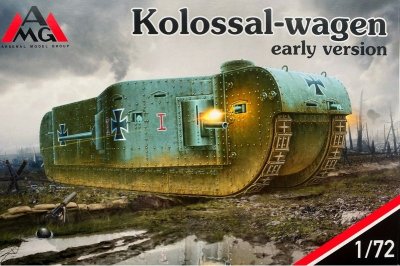
"The Großkampfwagen, also known as 'K-Wagen' for short, was a super heavy tank developed for the Imperial German Army in 1917, near the end of the first World War
(1914-1918), with the purpose of breaking through the stalemate of trench warfare that had already cost both the Entente and the Central Powers many lives.
It was an enormous vehicle, reminiscent more of a land battleship rather than a tank. Only two were partially built by the end of the war."
Weighing in at 120 tons, with a length of some 42 feet and possessing seven MGs and 4 cannons, size wise, it was close to 25% larger than the
German Maus tank of World War Two. With a projected top speed of 4.5mph (7.5kph), it would have made for a very large, slow lumbering target.
The Kit
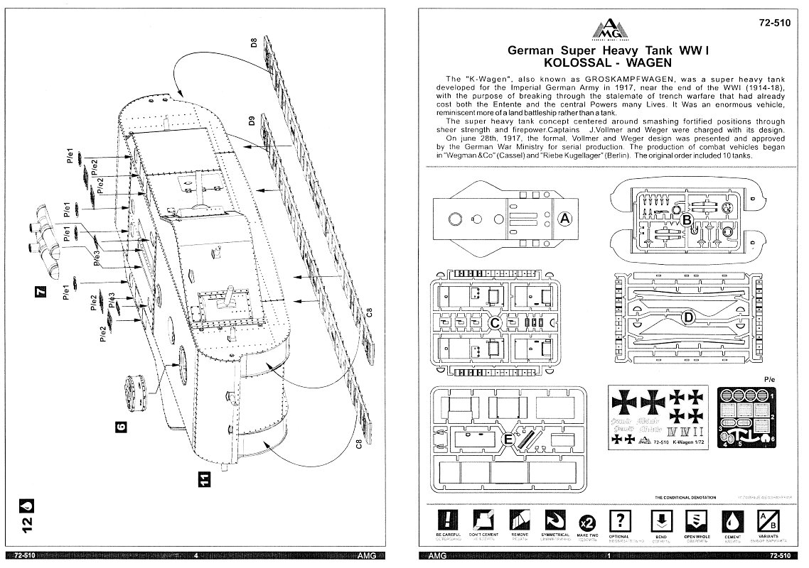
Sprue shots can be seen here at Henk of Holland
Box contains 4 injected plastic sprues (B=22 pieces, C=18 pieces, D=12 pieces, E=14 pieces: total=66 pieces) plus one large flat piece for the roof panel.
The plastic is light grey and quite soft. Thankfully all the parts are numbered on the sprues, unlike some other smaller manufacturers.
There is a small fret of etched copper detail parts (15 pieces) plus a decal sheet for two hypothetical tanks.
An instruction sheet
rounds out the contents. I felt it could be larger. The small diagrams being vague at times, making part orientation difficult.

Part design could have been better. For example, having the option to add the guns after the hull was assembled would eliminate the gun barrels getting in the
way during subsequent construction steps, and painting, where they could possibly be either broken, or worse yet, pushed into the body cavity while you work
on the model.
Parts have acceptable detail. On the other hand, most have some flash or a seam to remove. The MG barrels and flash hiders are out of round, but judicious sanding will
improve them to the point of being usable. There is no slide moulding here, so all body panels have a bevel where they meet. Sometimes a little scraping or sanding to
get pieces to align properly is required. There are a few unused parts: an extra C5 (bottom of the cannon nacelles); parts B3, B5 along with etched parts P/e5(x2) &
P/e6 (all possibly for an AA mount); and part B4(x4). I suspect these are all intended for a possible "late version" boxing edition of this kit?
Construction
I also felt that the instructions could not be trusted to get an acceptable build. Thus I followed a few steps as outlined, but deviated for much of the
construction of the body.
Before commencing, extra detailing included the following:
- drilled out muzzle ends for all of the MGs and cannons
- added sights to each MG barrel from small bits of plastic
- moulded on door and hatch handles were replaced with wire substitutes
- missing end pins on both sides of each track run were replicated with punched plastic discs
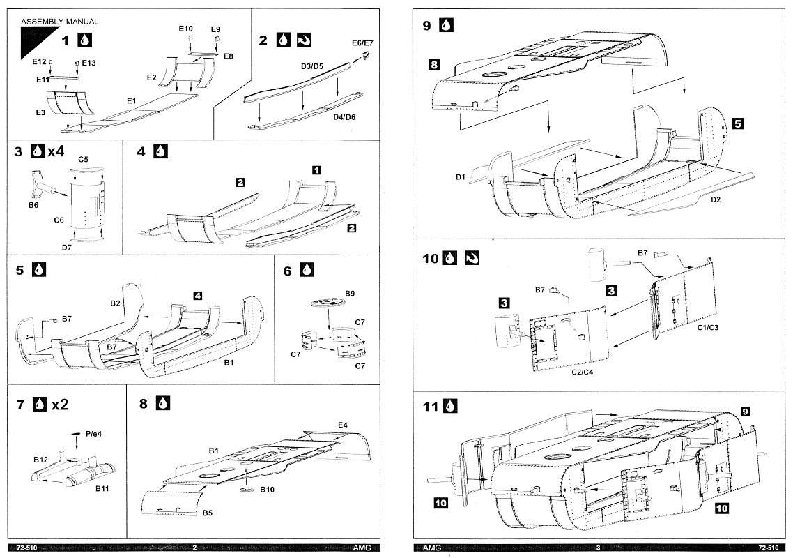
Steps 3, 6 & 7 were done as directed as they had little impact on the remainder of the build.
At Step6 pay close attention to the diagram. The small images make it difficult to determine which direction the hatch hinges should face on part D9.
The seams between the vertical panels
are particularly difficult to remove due the adjacent rivet heads.
With Step7 I drilled out the exhaust pipe ends before adding the etched grilles. It seemed to me that the grilles were a tad too large.
As for the remaining steps, I felt they were a potential recipe for disaster. Below outlines what I did.
Step1 was combined with Step2. I followed Step2 except I didn't add the end pieces (E6, E7). The vague instructions reared their ugly head here. There is no indication
as to which of parts D3/D5, D4/D6 & E6/E7 belong together.
The slash between the part numbers provides next to zero help for the builder. After some trial fitting I found that the right side parts are D3 & D6, and the left
side are D4 & D5. Next the Step2 sub-assemblies were joined to the belly panel (E1), followed by the end pieces (E6, E7), then by the remaining
Step1 parts: the front and rear belly panel end plates (E2 & E3) along with the other remaining parts (E9 through E13). Doing this makes Step4 superfluous.
Now comes Step 5. I didn't add the MGs (B7) here. They were added later. Step8 was also ignored as it too would be done later.
Time now to add the tracks, not as suggested in Step12. Each run consists of two sections, C8 for the front half and D9 for the rear half. The instructions are wrong in
showing the left track's rear half being part D8. The pieces are thick and their stiffness resists bending to follow the body channel, requiring their gluing
to be done in small increments, allowing the glue to firmly set before gluing down the next stretch. I did each of the four runs separately to ease clamping.
If I had waited till Step12 to install them, where all the guns are mounted, something surely would have been damaged.
Step9 through Step11 deal with the sponsons. Adding their floors as directed in Step9 didn't make sense. There was little surface area to get them squared up to
their sides, so I went off script as follows:
- First, off to Step10 to join the sponson side panel together. Once again in Step 10, the vague instructions leave one
with no idea which part pairs join to each other. The right side uses parts C1 & C2, while the left side uses parts C3 & C4. The parts are moulded
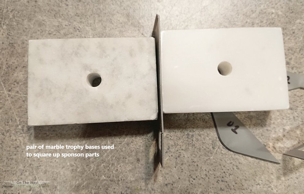
flat but eventually need to be bent to follow the floor's curve (D1, D2). So after they had dried thoroughly, they were glued to their respective floor.
With just the bevel to aid squaring up the join, I used a couple of discarded marble trophy bases to assist alignment as the glue set. (see photo below)
This proved to be a slow process as it required inching along the seam to ensure a solid join to eliminate any gaps between the panels. There's a groove on the backside
of each part to accommodate the necessary bends, but beware: the thin plastic can only be flexed so much before it will crack.
I removed the eyebrows over the large vision ports to ease seam sanding, though the eyebrows over the MG ports were left as they were.
Add the MGs (B7) from Step10 & cannon turrets from Step3 after the sponsons are attached to the body.
- Now return to Step9 to add the sponsons to the tank body. To aid alignment I glued sections of plastic to the vertical surface on the
left vertical body panel (B1) to stop the sponson from slipping in toward the interior. This worked well enough, but for the right side I also added plastic sections
to the floor (D1) to join up with the other vertical strips to make the sponson even more secure. (see photo below)
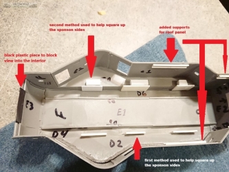
Another benefit to doing this was the additional strength it adds to the join. After everything was set nice and solid, I glued a set of five braces in
strategic locations along each wall to prevent the large roof panel (B1) from slipping into the interior when it came time to add it later. A small strip of
black plastic was glued to the front panel to blank off a view into the interior from the MG position. Before doing this, add the MG.
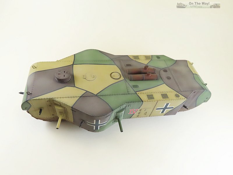
- The roof panels were next. Instead of joining all three large sections together as instructed in Step8, I started with the rear
panel (E4), then added the front panel (B5). This approach allowed me to properly align each panel with the sides. Now it was time to add the remaining ten guns while there
was still access to the interior. Afterwards, small strips of overlapping plastic were glued around each to prevent them being
pushed inside. The cannon turrets received the same treatment. For some interest, all guns were mounted at different angles.
Before adding the large panel (B1), hatch (B10) was glued in place. A trial fit showed that I need to trim approximately 0.5mm from the roof's rear edge
to get a flush fit. Sanding, scraping & filing along with much trial fitting resulted in an acceptable join.
Then the interior surfaces were painted flat black to hide all the white plastic inside. Adding the braces to the walls earlier saved a lot
of grief, as they reduced the tendency for the roof panel to fall inside the body, making clamping and gluing much easier. Once everything was set,
the roof and front/rear panels received lift rings obtained from the spares box.
Adding the copula from Step6 was next, then the photo-etch pieces. AMG's use of copper with its inherent flexibility versus much stiffer brass,
along with the parts being cigarette paper thin increased the difficulty level for removing the etch without damage. The rectangular grilles proved most troublesome.
They wouldn't easily fit into their assigned depressions, either due to them being oversized or their depressions being undersized.
On top of that, even with a sanding and cleaning with lacquer thinner prior to installation, their flexibility resisted my attempts to properly attach them using my favourite thin
cyanoacrylate glue. Eventually I had to resort to carefully removing them and then use Tamiya Clear acrylic paint as my glue. I had to clamp them down
with a piece of
parchment paper between the clamp and etched piece to ensure they stayed in place and didn't attach themselves to the clamp. The end result, to my eye, left a lot to be desired.
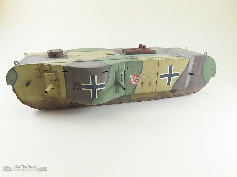
Markings & Decals
The decal sheet's vehicle markings are rather suspect. By 1918, the Iron Cross national markings had, for the most part, been replaced with the straight
armed Balkankreuze, so I substituted these with Superscale aircraft decals. I did use the kit's Roman numeral IV vehicle numbers. They proved to be excellent, settling down
superbly using Microsol solution over a gloss coat, leaving no trace of silvering. These are one of the best kit decals I've ever encountered.
References
[1] Waffen-Revue 52, I. Quartal 1984, Journal-Verlag Schwend, Schwäbisch Hall, West Germany, pp. 8342-8362
[2] wikipedia
[2] tank encyclopedia
Conclusion
AMG have to be recommended for releasing such an interesting subject. Some design choices could have been better to make the modeller's task somewhat less challenging
at times. With that said, a slow and well considered approach to construction will net the modeller a decent display model. If I was to build this kit again, finding
a better solution for the poor etched grilles would make a definite improvement to the model's overall look.
Review sample purchased by the author.
|