|
A Brief History:
From Special Hobby store:
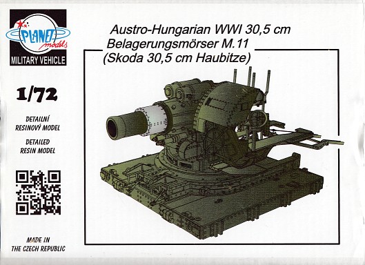
"The 30.5cm M.11 Mörser was a large caliber howitzer developed by Skoda Works between 1907 and 1911. In 1912, it was finally introduced to service as the M.11 Mörser.
The outbreak of World War One saw the Austro-Hungarian army equipped with as much as 24 of these guns. Possessing such high performance and being
of rather light weight (32.9 ton) made this weapon very unique, and what is more, it was possible to dismantle and transport the howitzer in three parts, making it
state-of-art piece with no real competition in its category. Because of these features, the weapon was used not only by the Austro-Hungarian army on the Russian and
Italian front, but it was also in service with the German army which borrowed four batteries, each with two guns together with their crews, and put them rather
successfully into action while conquering the Belgian fortified positions of Namur, Liege, Antwerp and Givet and also when the Germans bombarded Verdun and Toul
fortresses in France and Osowiec on the Eastern front."
In World War Two these howitzers were employed by the German's in their heavy artillery batteries, seeing
service in Poland, France and the Soviet Union.
The Kit
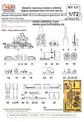
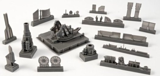
Contents comprise 39 resin parts plus 20 photo-etched parts, all contained inside a sturdy cardboard box. Resin parts come in medium
grey and for the most part are very well cast. There
are a few indistinct details on the base plus a few short shot areas. On my kit parts 26 and 27L & 27R were warped and needed straightening.
The barrel's two parts are a marvel of resin casting. The smaller details
are on the etched fret. This means that some of the items, such as the control wheels and sights will look rather 2-dimensional. It would have been better to offer
these in plastic or 3D prints. PE parts are thin and flexible, making removal from the frame and gluing together somewhat difficult.
No decals are present nor would they be expected. Instruction sheet has 8 steps with a few sub-steps. They
are of the old fashioned exploded diagram variety, which I found somewhat ambiguous with the arrows used to indicate part placement
confusing in places.
The Build
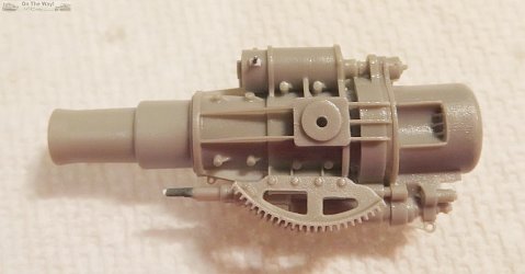
I started as directed, with Step 1. The only item of note here is that the elevation gear arcs located on the underside of the
barrel need to have their flashed over depressions opened up. A couple of protruding parts underneath were not cast well and were rebuilt.
Parts 30 were poorly moulded, so they were replaced with small strips of plastic and wire. Sections of the base towards the towing loop and between the large beams are so
thinly cast that they had voids which required filling, a difficult task given the limited space available.
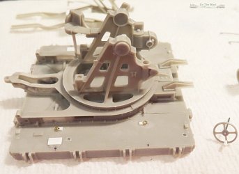
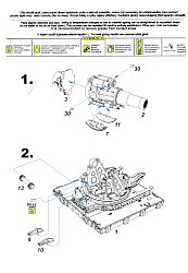
At Step 2, some changes were made. The rectangular inspection panels and the mounts for the rings on the base were rather indistinct so they
were replaced with thin plastic card. The rings were replaced with left over brass items from the spares box. I saved the elevation gear
(part 13) for mounting later, and I didn't add the small resin brace for the gunner's protective hood (PE part 15) nor its resin
alternative. I found only one war time photo on the web showing the hood mounted. Make sure to drill out the flashed over towing loop hole.
|
|
Step 3 was skipped. A test fit of the barrel revealed that there was just enough flex in the mount's side panels to allow me to add the barrel
at the end of the build. With the barrel's absence, I could paint the nooks and crannies without the barrel blocking my airbrush's spray. I also didn't
mount the second brace for the protective hood (PE part 5).
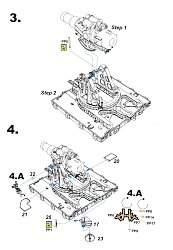
For Step 4/4A, only the sight's mount (part 32) and the two parts for the traverse wheel housing (parts 17 & 23) were added. The two
operator platforms (parts 20 & 21) were left on their casting blocks to ease painting, then to be added as one of the last tasks
to complete the build. The post supporting the traverse gear was replaced with section of plastic rod as it was out of round.
Traverse wheel (PP1) was replaced with one from my spares box. |
|
Next came Step 5. Before construction commenced, I replaced the poorly cast walking surfaces on the loader platforms (parts 28 & 29 ), plus added some extra detail in
the form of a U-shaped loop taken from my spares box. These loops would eventually receive the loader platform's supporting rods.
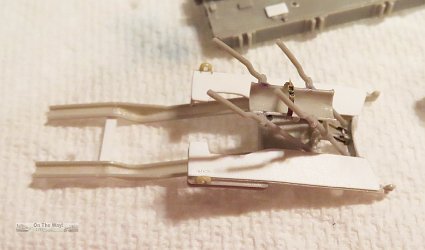
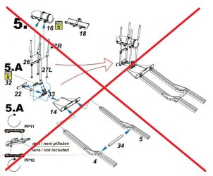
I felt Step 5 was questionable regarding its suggested assembly sequence, which in my mind was a recipe for disaster. The sub-assembly created
here looked to be difficult to align properly and too flimsy to work with later without causing damage. On top of that, the loaders
platforms were added at Step 7 with no arrows directing the builder as to where exactly they should go in relation to this sub-assembly. So I tried deviating here but my
efforts just led to parts not aligning properly. After some thought, I grabbed instructions for the CMK 1/35 scale kit from the web.
These were much
more logical in their construction approach and revealed where I went wrong. To get this kit back on track I had to break apart my previous work which caused some
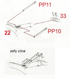
damage. Fortunately nothing major was destroyed beyond repair. A replacement was fashioned for partially broken part 22 and I proceeded, following the 1/35 scale
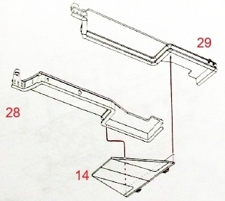
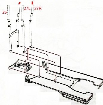
instructions, which I have altered to add the relevant 1/72 scale part numbers (see at right).
So, I hope the altered instructions at right illustrate my eventual method to get all the parts in the proper places:
- Glue parts 28 & 29 (left & right side loader platforms) to part 14. There are raised edges on part 14's topside
that can be used as guides to position the two platforms.
- Then add parts 22 & 23 to part 14. Part 22 fits neatly between the two loader platform pieces.
- Now comes the fiddly PE parts, PP10 & PP11 and the wire (not supplied) to be placed between the two arms of the lock.
This wire needs to be about as thin as a human hair. I used
a short section of plastic rod instead. It is out of scale, but trying to get a wire in place here would likely make one pull their hair
out in frustration. Next add the ammo support arms (parts 26, 27L & 27R). These were warped at their tops in my kit and required straightening.
- Lastly, add the ammo cart ramp rails (parts 26, 27L & 27R). I suggest replacing the much too thin and flexible part 34
that spans the gap between the rails with plastic channel.
There are optional parts for the shell tray: with and without a shell in the tray. Not relishing the idea of painting a moulded on shell, I
opted for using the empty tray (part 18). The strap was not cast well so I replaced it and the associated clamp with PE from my spares box.
The strap was broken so it was replaced.
With the loader platforms glued to the gun's mount I was now able to build the rather obvious loader platform's support rods.
Nothing is included in the box for them and there is no guidance in the
instructions as how to make some. If you do scratch build them as I did, they eventually run diagonally from the rear of the loader platforms
up to the mount. Though it's not indicated in the instructions, there is actually a small triangular spots moulded on each side of the mount frame
to where they should attach.
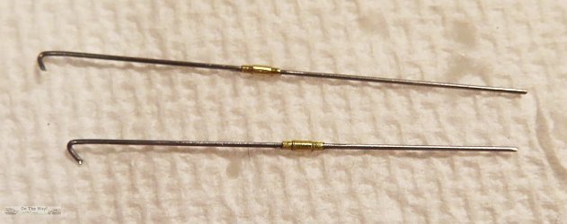
My scratch built versions were cut from piano wire, 0.35mm in diameter, One end on each was bent to form a hook to fit inside the loop I had added to each
loader platform earlier. The right side length is 35.75mm. The left side was a couple of millimetres shorter. Just as I had to do, you will need to
fine tune the length to get a proper fit. The tighteners were fashioned from two diameters of brass tubing from Albion Alloys.
The inside tube is 2.6mm long (diameter 0.63mm) and the outside tube is 1.5mm long (diameter 0.79mm).
|
|
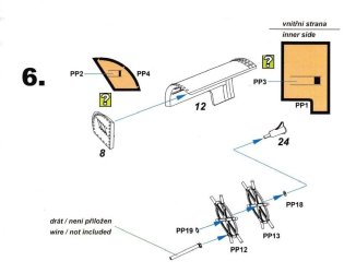
On to Step 6. Only the elevation wheel was completed. As mentioned earlier, the parts for the protective hood were not planned to be used.
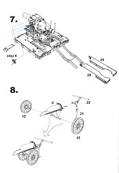
Step 7 is superfluous. The loader platforms would already be in place from Step 5.
By the time I reached Step 8, my patience with this build had worn thin. I decided I didn't want to put the effort into building the ammo
transportation cart, not relishing the removal of the flashed over holes between the wheel spokes.
Accidentally stepping on part 6 settled the
matter as it was crushed beyond repair. For those that do build the cart, make sure to add an axle. One isn't supplied, nor shown in the instructions.
|
|
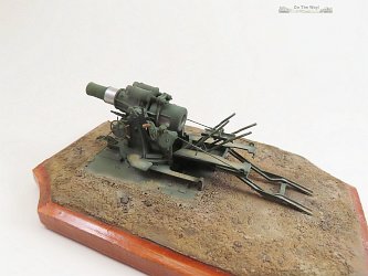
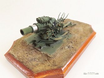
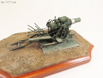
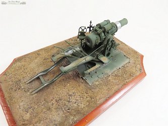
Now to the final steps. This included painting, weathering, adding the loose parts, and in my case mounting the gun on a base and adding some groundwork.
The loose parts were all painted separate from the main body. These include the barrel, elevation gear, control wheels, small operator platforms, gun sight and
bracing rods to the large loader platforms.
Conclusion:
This one is definitely not for the faint of heart. Having a few resin kits under your belt would be helpful for constructing this kit. With some patience a great looking model
of this historically important piece of artillery can be had.
References:
[1] landships.com
[2] wikipedia
[3] super-hobby.com
(useful 1/35 scale instructions can be found here)
Review sample purchased by the author.
|
